Dynamic Routing Demonstration Using CISCO PACKET TRACER and RIP
Dynamic routing is all about configuring a network using dynamic routing protocols.
Dynamic Routing Protocol is divided in to two main parts.
1.Interior Gateway Protocol
2.Exterior Gateway Protocol
In this section will look at Interior Gateway Protocols.
-this is an autonomous system and handled by only one admin.
-this protocol is also divide into two parts,
1. Distant Vector Protocols(Bellman-Ford Algorithm) - distance is measured by `hop count` and use for simple networks
2. Link State Protocol(Dijkstra Algorithm) - this uses some other information like neighbour router info and this is best for complex network designs
In this Scenario we are using Routing Information Protocol(RIP) as the dynamic routing protocol.
So below mentioned diagram is the network plan for a small network.

In this Network diagram,
192.168.10.0 , 192.168.30.0 , 192.168.20.0 , 10.0.0.0 , 11.0.0.0 are 5 different networks.
Router 1, Router 2, Router 3 are routers in this network.
PC 1, PC 2, PC 3 are computers(end devices) in this network.
Black dashed lines are Copper Cross-Over cables which uses to connect different type devices.
Red colour lines are Serial DCE cables which are building the connection between two routers.
PC 1 - IP Address: 192.168.10.1(Fast Ethernet 0/0)
Default Gateway : 192.168.10.100(Fast Ethernet 0/0)
PC 2 - IP Address: 192.168.30.1(Fast Ethernet 0/0)
Default Gateway : 192.168.30.100(Fast Ethernet 0/0)
PC 3 - IP Address: 192.168.20.1(Fast Ethernet 0/0)
Default Gateway : 192.168.20.100(Fast Ethernet 0/0)
Router 1 - IP Address(SERIAL 0/2/0) : 10.0.0.200
IP Address(SERIAL 0/2/1) : 11.0.0.200
Router 2 - IP Address(SERIAL 0/0/0) : 10.0.0.100
IP Address(Fast Ethernet 0/0) : 192.168.10.100
Router 3 - IP Address(SERIAL 0/0/0) : 11.0.0.100
IP Address(Fast Ethernet 0/0) : 192.168.20.100
After configuring these IP addresses to the corresponding devices only, we should configure dynamic routing to the network.
When doing dynamic routing using RIP protocol first we should identify the networks which are connected to each router and for those routers we have to connect those networks through RIP.
So below mentioned procedure will guide you to do the RIP dynamic routing.
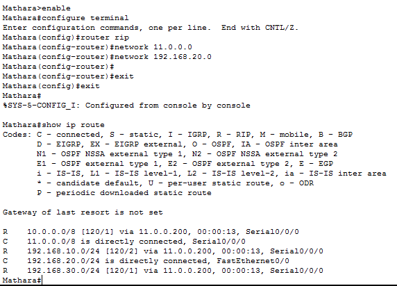
1. Router 1 configuration steps.

The below figure shows us the routing table which is updating periodically.
C- directly connected networks are marked as C.
R- networks which connected using the RIP dyanamic routing

Below two figures are showing us the current running configurations of the router 1.


2. Router 2 configuration steps.

3. Router 3 configuration steps.


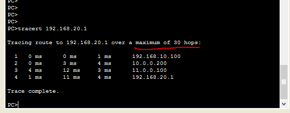
In this figure it shows the path to the destination device(PC 3) from source device(PC 1).
for this we are using TRACERT <DESTINATION IP ADDRESS>(TRACEROUTE) and it will show us the complete path and the time consumed to transfer data.

Dynamic Routing Protocol is divided in to two main parts.
1.Interior Gateway Protocol
2.Exterior Gateway Protocol
In this section will look at Interior Gateway Protocols.
-this is an autonomous system and handled by only one admin.
-this protocol is also divide into two parts,
1. Distant Vector Protocols(Bellman-Ford Algorithm) - distance is measured by `hop count` and use for simple networks
2. Link State Protocol(Dijkstra Algorithm) - this uses some other information like neighbour router info and this is best for complex network designs
In this Scenario we are using Routing Information Protocol(RIP) as the dynamic routing protocol.
So below mentioned diagram is the network plan for a small network.

In this Network diagram,
192.168.10.0 , 192.168.30.0 , 192.168.20.0 , 10.0.0.0 , 11.0.0.0 are 5 different networks.
Router 1, Router 2, Router 3 are routers in this network.
PC 1, PC 2, PC 3 are computers(end devices) in this network.
Black dashed lines are Copper Cross-Over cables which uses to connect different type devices.
Red colour lines are Serial DCE cables which are building the connection between two routers.
PC 1 - IP Address: 192.168.10.1(Fast Ethernet 0/0)
Default Gateway : 192.168.10.100(Fast Ethernet 0/0)
PC 2 - IP Address: 192.168.30.1(Fast Ethernet 0/0)
Default Gateway : 192.168.30.100(Fast Ethernet 0/0)
PC 3 - IP Address: 192.168.20.1(Fast Ethernet 0/0)
Default Gateway : 192.168.20.100(Fast Ethernet 0/0)
Router 1 - IP Address(SERIAL 0/2/0) : 10.0.0.200
IP Address(SERIAL 0/2/1) : 11.0.0.200
Router 2 - IP Address(SERIAL 0/0/0) : 10.0.0.100
IP Address(Fast Ethernet 0/0) : 192.168.10.100
Router 3 - IP Address(SERIAL 0/0/0) : 11.0.0.100
IP Address(Fast Ethernet 0/0) : 192.168.20.100
After configuring these IP addresses to the corresponding devices only, we should configure dynamic routing to the network.
When doing dynamic routing using RIP protocol first we should identify the networks which are connected to each router and for those routers we have to connect those networks through RIP.
So below mentioned procedure will guide you to do the RIP dynamic routing.
1. Router 1 configuration steps.

The below figure shows us the routing table which is updating periodically.
C- directly connected networks are marked as C.
R- networks which connected using the RIP dyanamic routing

Below two figures are showing us the current running configurations of the router 1.


2. Router 2 configuration steps.

3. Router 3 configuration steps.
After Configuring three routers as above mentioned, we can now send packets through one end to another. To check whether it is working we can check by ping command.
PING command can check the connection between two end devices and have to execute in terminal of the source device.
PING <IP address of the destination>
Now we will just get an example to demonstrate this scenario.So for that will take PC 1 as the SOURCE DEVICE and PC 3 as the DESTINATION DEVICE.
PC 1 IP- 192.168.10.1
PC 3 IP- 192.168.20.1
In Below figure we can see that the data packets transfer and the data packets which have lost their path.

In this figure it shows the path to the destination device(PC 3) from source device(PC 1).
for this we are using TRACERT <DESTINATION IP ADDRESS>(TRACEROUTE) and it will show us the complete path and the time consumed to transfer data.
So this will End up the Dynamic Routing Session :) Hope you got some knowledge from this section
:)
Below Video is a Demonstration of a packet transfer corresponding to the above network diagram.

Maxxa Macha ....
ReplyDelete